These are some miscellaneous photos and possibly helpful tips from my stereo install. I was down to one functioning speaker on my OEM Bose system. I wanted a replacement system that made use of all the stock "holes" for the speakers and head unit. I valued clean sound over deafening decibels. Plus, I wasn’t willing to sacrifice any of the meager storage space we have in our cars in the name of a new stereo.
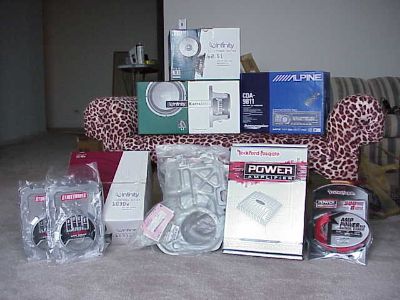
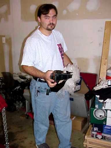
Here's all the "stuff" sitting in my apartment, ready for the install:
Top row: Inifinity Kappa 2-way 6.5" speakers for the rear
Middle (L to R): Infinity Kappa Perfect component 6.5" speakers (with tweeters) for the front; Alpine CDA-9811 CD/MP3/WMA head unit
Bottom, on floor (L to R): 2 packs RCA StreetWires Low Noise cables; Infinity Reference 1030w 10" sub woofer, final price $9.99 after Internet misprint rebate which I did not install; OEM Nissan front speaker brackets to replace the Bose boxes in the doors, Rockford Fosgate 551X 70W X 4-channel amplifier, Rockford Fosgate CP8Pi amplifier wiring kit. Not shown are the Nissan wire harness, the Nissan antenna adapter, and a bunch of 16 gauge StreetWires speaker wire.
 Close-up of a front Kappa Perfect component speaker, tweeter and crossover. Good stuff. Close-up of a front Kappa Perfect component speaker, tweeter and crossover. Good stuff.
Cost of this system was right at one thousand bucks, shipped. Shopping around saved me a lot of money. Crutchfield's price on the head unit was as good as anyone's, especially when they threw in free shipping, the harness, the antenna adapter, some excellent written instructions, and lifetime tech support. Otherwise, I just went with whichever on-line vendor had the cheapest price, and I saved hundreds.
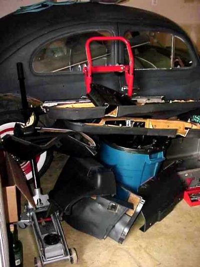
The pile of junk is actually my car's interior pieces.
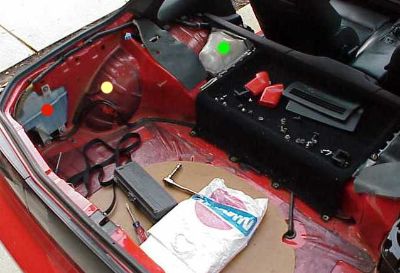
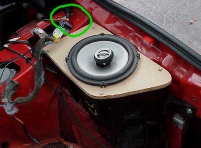
Here is the rear hatch area with most of the trim pieces out - the red dot is over the windshield washer reservoir. The driver's side rear speaker box was sitting over the part of the wheel well marked by the yellow dot, but it has already been removed. The green dot is over the infamous Spiderman Super Wall Climber Kit, otherwise known as the headlight aiming tool kit that freaks noobs out when they stumble upon it. The Nissan bag contains the most important tool of all, a service manual.
Moving toward the front of the car, here are a couple of excellent links to door panel removal, which is necessary in order to get the speakers out. Do not try to remove the speaker covers separately. They are built into the door panels.
door panel removal as part of a stereo install
door panel removal translated from Japanese
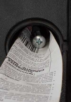
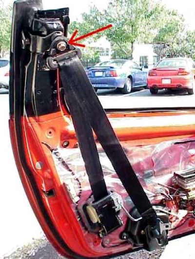
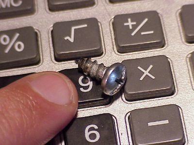
This is my trick for not losing the screw that goes through the outside door pillar, underneath the small, round, plastic garnish piece shown by the green arrow. The round garnish piece pries off easily. The screw underneath has to be removed to get the interior door trim off.
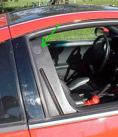
Simply make a little ramp out of some curled cardboard so if the screw falls at any point, it slides out. If it falls in between the body panels, it can be very difficult to retrieve.
As you may notice, the screw in the photo is not stock because I lost that OEM screw-bolt in the body panels long ago, which is how I learned my lesson, lol.
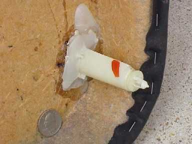
I broke off one of the trim fastener posts that held the door panel in place with my usual delicate touch, during the removal. The white glue is original. The wet looking, clear stuff is the quick setting 2-part epoxy I used to fix it. Fascinating, isn’t it?
I was at Bernie's house when I started this job. By the time he got out of bed, I had the front and rear interior out and ready for the install, lol. Suffice it to say that he and I are on different biorhythms :c) His help, space and tools were invaluable. Thanks as always, Bernie.
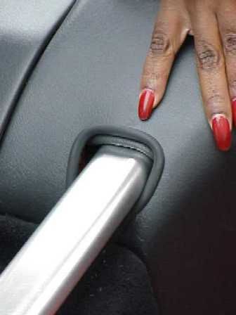
After the door panels were removed, I finally figured out I could finger tighten the upper seat belt bolt on each door back into place. This accomplished two things: it kept the umpteen washers and spacers on that bolt from falling off and getting lost (mine fell apart and were rolling around a Home Depot parking lot) and it made the seat belt useable and legal for driving.
This photo shows the modification necessary to the OEM front speaker replacement brackets. The bracket on the left is for the driver's side. The corner circled in green had to be cut out with a Dremel tool on both pieces, so that it would fit around some cables and wires already in the door. The bracket on the right has not been cut yet, for comparison. The backs of the brackets are shown.
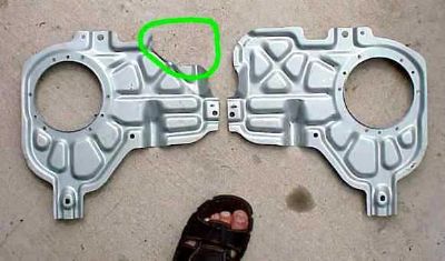
This photo shows the same bracket installed, and why the cutout was necessary. Those cables and wires don't have anything to do with the stereo, but they do prevent the bracket from lying flush, unless you cut it. I used Dynamat insulation wherever there was metal touching metal on the back of the mounting bracket to eliminate any potential rattles or buzzes.
Clearance problems are very common when installing new rear speakers in the stock factory boxes. I went through the trouble to buy '90 speaker boxes because they have 6 1/2" round cutouts for the speakers. All the remaining z32 years used a much smaller, 3 1/2" round speaker in the back. However, even low profile aftermarket speakers can and will rub the trim piece that goes over them.
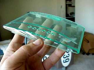
I found the easiest and cleanest solution was to take the tops off the boxes and put in a flat soundboard instead. This eliminated the port in the speaker top, but the aftermarket speakers were not designed to be ported anyway. Plus, you can cut whatever shape and size speaker hole you want in the board. This fix also makes having to obtain the '90 boxes a moot point, since you can do this mod to a rear speaker box from any year. The photo shows the old top to the speaker box. The bottom of the box with the new speaker and top can be seen installed in the car, in the background.
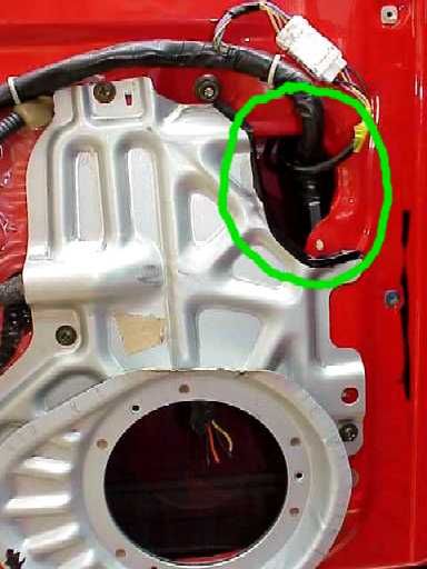
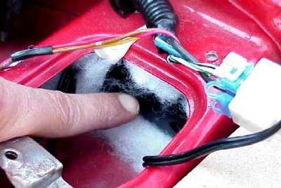
The crossover for this rear speaker was hidden under the interior body panel shown circled in green. The crossover was held in place with a single, plastic cable tie. I stuffed some poly-fill around it for padding and to prevent any rattles, for a nice, clean, tight, hidden installation.
 Close-up of the crossover for the rear, right speaker, circled in green in the above photo. Close-up of the crossover for the rear, right speaker, circled in green in the above photo.
Here are the wires leading to the rear speakers as they originally existed in the car, a '92 TT. The wiring can be a little confusing since the OEM Bose speakers each had their own amplifier. This meant there four wires going to each speaker. There is a screwdriver under the speaker wires to isolate them for the photo. The speaker wires were white with a green stripe, and brown with a white stripe. They were also noticeably smaller in diameter than the remaining two wires in the bundle that went to the amplifier. The colors of the amplifier wires can be seen under the screwdriver as solid brown for one wire, and green with a white stripe for the other wire. You do not use those.
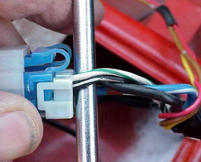 The wires are shown plugged into a clip that came with the '90 speaker boxes. The blue part of the clip (the car side) had to be shaved slightly with a Dremel in order to fit into the white part of the clip (the speaker box side). The wires are shown plugged into a clip that came with the '90 speaker boxes. The blue part of the clip (the car side) had to be shaved slightly with a Dremel in order to fit into the white part of the clip (the speaker box side).
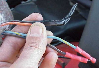
Of course, you can cut off the blue and white connectore shown in the photo above and splice directly into the proper colored wires. The speaker wires that came with the '90 boxes were blue with a yellow stripe, and brown with a blue stripe. The amplifier wires were solid dark brown, and solid orange, and are shown taped off.
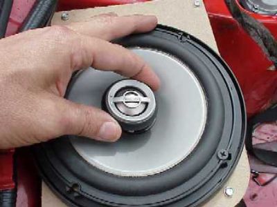
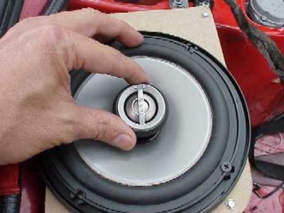
The next two photos show a neat little feature of the rear speakers. The tweeters were angled, and could be aimed by simply turning them. They had a built in ratcheting, swivel mechanism. I did the obvious and aimed the toward the front.
Here's a little piece I had sitting on the shelf for awhile. Seemed like a good time to throw it in, since the rear strut towers were staring me in the face :c)

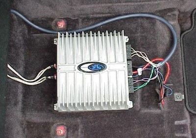
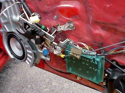
This photo shows the front passenger side, seat removed, door panel removed, and center console removed. The new, front speaker bracket is in place and the amplifier is sitting in its new home, to be hidden under the passenger seat. I'm trying to figure out where to put the front crossovers. The amplifier came with endcaps that I did not use since it made the amp quite a bit wider. Without the endcaps, the size of the amp was H=2.358", D=9.847", W=9.766", and it fit nicely under the passenger seat. With the endcaps, the unit was aprox 2 ¼” wider, or longer since I had the ends pointed toward the front and back of the car.
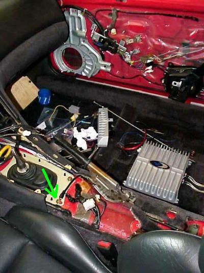 The amp is grounded to the shifter plate, shown by the green arrow. The amp is grounded to the shifter plate, shown by the green arrow.
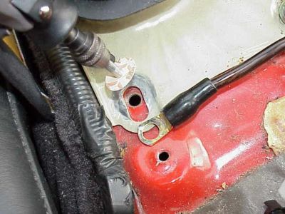 Close-up of main stereo ground on shifter plate. Do not ground to painted metal. Close-up of main stereo ground on shifter plate. Do not ground to painted metal.
I could hear a huge difference in the bass response after I went back with my Dremel and exposed the bare metal underneath this ground.
Just in front of the amp, the power cable from the battery and the wires from the head unit can be seen exiting the carpet. That hole in the carpet was already there. The RCA cables exit the back of the amp, go under the panel that is behind the passenger seat back, then up through the center console between the seats to get to the head unit.
 I just used short metal screws to secure the corners of the amp to the carpet. The screws do not go into the metal floor pan, just the carpet and pad, and the amp does not move, even during trips to the track. I just used short metal screws to secure the corners of the amp to the carpet. The screws do not go into the metal floor pan, just the carpet and pad, and the amp does not move, even during trips to the track.
 This is passenger floor, seat removed, with the front of the car to the right side of pic. This is passenger floor, seat removed, with the front of the car to the right side of pic.
The greyish-blue cable at the top of the pic can be purchased separately as Speedwire, which combines several color coded wires in a single outer insulation.
The red power cable in the above pic is connected directly to the positive pole of the battery.
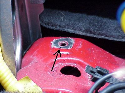
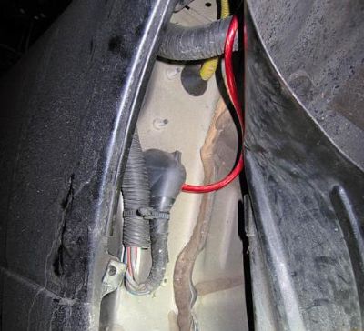 The cable gets into the passenger compartment through this grommet hole, behind the passenger side fender well. The plastic fender has to be peeled back just enough for access. Pic courtesy of Ashley. The cable gets into the passenger compartment through this grommet hole, behind the passenger side fender well. The plastic fender has to be peeled back just enough for access. Pic courtesy of Ashley.
A valuable tool is a thin, long flexible grabber, used for snaking wires under the carpet. I did not have to lift any carpet or cut any holes thanks in large part to this tool. The tool is a few feet long, bends, and has a plunger on the other side that works the "claw" shown. Worth the six bucks it costs at Sears or any auto parts store.
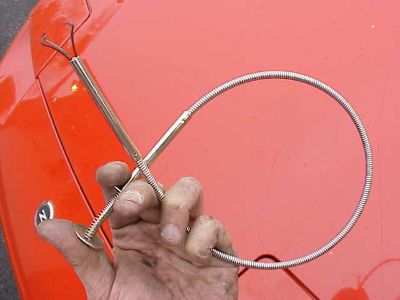 Yeah, that's my z31 in the background but this was a better pic of the tool :c) Yeah, that's my z31 in the background but this was a better pic of the tool :c)
The crossovers to the front speakers had removable lids.
I tried everywhere but I couldn't get the door panels to reinstall properly with the crossovers mounted behind them. The crossovers were too thick. I was thinking of hiding the crossovers elsewhere in the cabin, but they are supposed to stay as close to the speakers as possible. So I mounted them with their lids removed, "open face" against the door. The pic shows the green back of the crossover to the right, and the new speaker and bracket to the left in the passenger door.
Since they were not water tight even with their lids on, and they are flush up against the plastic, I'm hoping that this still gives them all the protection they need from the elements.
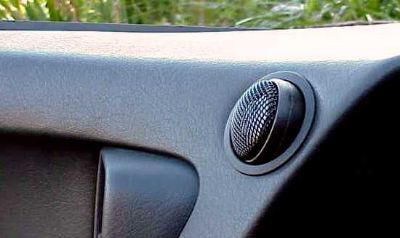
Here are the front tweeters. Notice that I have them angled so that they are pointed straight at the driver's ears. These tweeters could be swiveled within their mounting brackets, which was a great feature. At first, I installed them just pointing straight out from their holes. Aiming them in the way shown made them sound noticeably better. I cut the holes with a Dremel using the template that came with the speakers. The fit was a bit snug behind the tweeters, but definitely doable. As they say, measure twice, cut once :c)
 driver's side door open, side view, front of car to right driver's side door open, side view, front of car to right
 view from the driver's seat with the door closed view from the driver's seat with the door closed
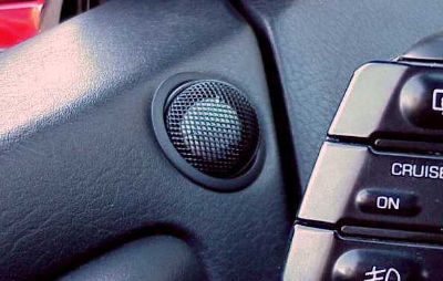
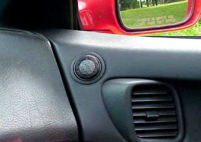 the passenger side tweeter, view from the driver's seat the passenger side tweeter, view from the driver's seat
I opted not to go for the "stealth" install with the tweeters behind the vents after trying it that way first, and comparing that sound to having the tweeters out in the open, as in the above pics. I also talked to a few experts, as in stereo installers and a Bose sound engineer. The high notes from the tweeters are directional, and are effected very much by the objects around them, or in the case of the A/C vents, in front of them.
The high sounds are literally the opposite situation of the low frequencies from a subwoofer, which are omnidirectional. A sub can be placed almost anywhere in the listening environment and the point source for the sound is not discernable. In contrast, tweeters should have a clear sound path to your ears.
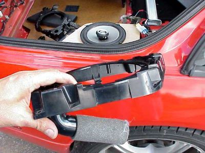
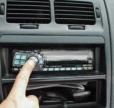
Head unit install involves removing this center dash piece held in place by four screws.
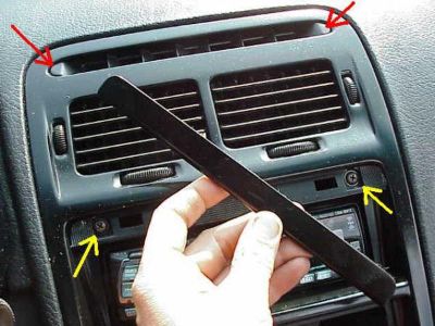 The red arrows point to little trim pieces that pry off and reveal two screws. The long skinny trim piece in my hand goes over the yellow arrows. The red arrows point to little trim pieces that pry off and reveal two screws. The long skinny trim piece in my hand goes over the yellow arrows.
I used Velcro to hold the piece in my hand in place. After the screws next to the arrows are out there are still prawl clips holding the trim piece in place.
Nice, clean, tight, install of the head unit (HU), thanks to Bernie modifying the mounting brackets with new screw holes, so that the face plate was flush with the DIN opening.
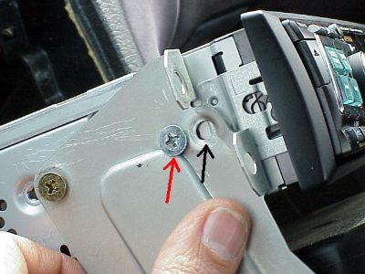 The red arrow is where the new screw hole was drilled, the black arrow was the original mounting hole. The red arrow is where the new screw hole was drilled, the black arrow was the original mounting hole.
So the front of the HU was moved forward by the distance between the two arrows.
 There is an excellent stock ground location behind the head unit that I reused. Be sure to scrape some paint away to expose the bare metal. There is an excellent stock ground location behind the head unit that I reused. Be sure to scrape some paint away to expose the bare metal.
I reused the stock ground wire and spliced it into the new ground from the HU.
 HU sat at just the right depth in the dash. HU sat at just the right depth in the dash.
My Carbing rear strut bar installed with the hatch trim back in place. The "layer" between the cut out in the trim and the bar is the soundproofing material that was glued to the underside of the trim piece. I removed it, flipped it over, and folded it back onto itself to fill the hole, help with the sound insulation, and pad the bar a bit. I like the finished look it gave the install, too.
I'm very happy with the sound from my new stereo, although just like the car in general, I got used to the new amplifier pretty fast, and am hungry for more power ;c)
|